

Wednesday, December 30, 2015
Monday, December 28, 2015
Layout Update Mondays: Wiring
 | |||
| The underside of the MOW module section. |
Wednesday, December 23, 2015

Monday, December 21, 2015
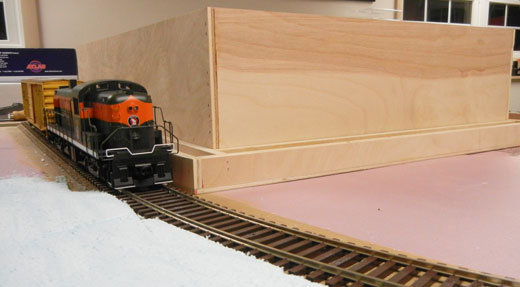
Layout Update Mondays: First Texture
 |
| Initial scenery on the MOW module. |
With only five weeks (!) left until show time, I am starting to prioritize what portions of the layout I would like done for this year and what will have to wait until next year. While I hadn't planned on having everything complete for this year, in general, I like to bring a layout where there is at least a basic level of scenery completed. With a few more days of work, I should be pretty close to having this base coat of scenery applied to all 44 square feet of layout.
Friday, December 18, 2015
Figure Fridays: Rail Crew
 |
| The O Scale Rail Crew for the Tribute to Springfield. |
One of the focal points of the layout will (hopefully) be all of the figures which will help tell the story of the Railroad Hobby Show.
The first set of figures I have finished for the layout is the rail crew. The figures started as the Bachmann O Scale Mechanics. In order to modernize the figure set, each figure was repainted to have a safety vest (the modern green version) as well as change some of the colors of the pants and shirts. These simple revisions completely changed the look and feel of the original figure set.
Monday, December 14, 2015
Layout Update Mondays: Painting
 |
| Base painting completed on the modules. |
Friday, December 11, 2015
History Fridays: 1997 Railroad Hobby Show
Before the Wiscasset, Waterville & Farmington Railway Museum was wowing the crowds at the show with their full size narrow gauge dairy car, vendors in the Young Building got quite a show each year in the late 1990s and early 2000s. During this time period, one of the members of the Mohegan Pequot Model Railroad club was a commercial truck driver. He worked for a moving company and had access to a tractor and 53' trailer. Since it was the slow season for the moving company, they agreed to donate the use of the trailer to the club for about a week around the show. The Wednesday before the show, the club would pack up its HO and G scale layouts inside the trailer. Early Friday morning, the tractor trailer was the first entrant into the building as club members would race to unload so other exhibitors and vendors could enter and begin their setup. After the show on Sunday, the tractor trailer would be the last vehicle into the building as many vendors needed to do move out before there was enough room to enter the Young Building.
This was certainly an unusual sight for those working in the Young Building and would bring everything to a stop as the big doors were opened and the rumble of the tractor-trailer filled the building. The first year the club was able to use the trailer was 1997 (which is shown in the video above). For eight years, this was the routine. While today the club simply has its members bring their own modules - typically in personal vehicles - this was a fun behind-the-scenes story for a number of years of the show.
Thursday, December 10, 2015
Exhibitor Thursdays: Mohegan Pequot G Scale
 |
| Mohegan Pequot G Scale Layout at the 2011 Railroad Hobby Show. |
Exhibitor SpotlightName: Mohegan Pequot - G ScaleYears at the Show: 20 Display Style: Modular Layout Type: Model Railroad Club Size: 38'x58' Present Location: Young Building Past Location: N/A Home Location: Ledyard, CT Website: MPRR Club Social Media:   
|
Over the last 10 years or so, the club has been partnering the with the Central Connecticut G Gaugers to help bring a larger and more impressive layout to shows. This influx of members has kept the group active and attending events in New England as well as shows as far away as Pennsylvania.
At the Railroad Hobby Show, the group display's a 38'x58' layout inside the Young Building. Traffic is always busy and the large size of the trains certainly draws a crowd. Over the years, the group has steadily added to the display with new animated scenes. For example, the layout has included a working drawbridge, intermodal crane, and even a drive in movie theater. There are some rumors that a working rotary dump module is in the works and might just make it to the show this year...you'll have to stop by the show to find out!
To learn more about the club, visit the website at: www.mprr.org
Wednesday, December 9, 2015

Monday, December 7, 2015
Layout Update Mondays: MOW Details
 |
| MOW area in progress. |
Wednesday, December 2, 2015

Monday, November 30, 2015
Layout Update Mondays: Young Building
 |
| The Young Building under construction. |
Wednesday, November 25, 2015

Monday, November 23, 2015
Layout Update Mondays: More Landforms
 |
| Foam glued in place on the Slide and Mallary Complex Building modules. |
The next step was to glue foam insulation in place. This was done with both carpenters glue and hot glue. The hot glue acts as a temporary clamps so work on shaping the foam can happen quickly. The carpenters glue takes a few days to dry but creates a strong bond. I've tried hot glue on its own but found that over time (usually several years), the foam will delaminate - not ideal for a modular layout.
The final step was to shape the foam to the desired contours. I used several tools like a back saw, key hole saw, and various surform tools to complete the job.
 |
| Shaping the foam with a surform tool. |
 |
| The final contours on the module. |
Wednesday, November 18, 2015

Monday, November 16, 2015
Layout Update Mondays: Trackwork Complete
 |
| An overview of the completed trackwork. |
 |
| The siding on the Slide module. |
Now, back to the shop to finish the wiring!
 |
| Revised railroad headquarters building. |
Wednesday, November 11, 2015

Monday, November 9, 2015
Layout Update Mondays: Paving Memorial Ave.
 |
| Adding drywall mesh to the road base. |
 |
| Sculptamold applied to the road surface. |
 |
| Another view of the Gate 9 entrance driveway. |
Wednesday, November 4, 2015

Monday, November 2, 2015
Layout Update Mondays: Weathering Track
 |
| Track weathered and ready for service. |
 |
| Step 1: Distress track, detailed and ready for paint. |
 |
| Step Two: Paint Ties a light gray color as a base. |
 |
| Step Three: Paint rails a rust color. |
 |
| Step Four: Paint some ties a black color to represent ties which have recently been replaced. |
 |
| Step Five: After ballast has been glued down, dry brush black down the center of the rails to represent oil and grim left by the slow speed switching movements of the locomotive in this area. |
Now, back to completing the trackwork on the rest of the modules so trains can be running soon!
Wednesday, October 28, 2015

Monday, October 26, 2015
Layout Update Mondays: Connector Tracks
 |
| Overhead view of a connector track between the Memorial Ave. and MOW modules. |
Most modular railroad clubs use connector tracks - short pieces of track which are made to be removable that connect to the permanently affixed track on the module sections. The connector track offers some flexibility as it is difficult to build really tight tolerances among various builders over time. Having a connector track means that the rails don't have to be lined up perfectly on the module sections as the connector track takes care of the minor deviations between the modules.
Unlike a modular layout, this layout has the advantage in that it will always be setup in the same orientation every time. This style of portable layout could lend itself to simply having the track line up flush at the end of each layout section. While I've seen sectional layout builders pull this off, I'm kind of skeptical about how well this works in varying temperature and humidity environments. Plus, between the Memorial Ave. and MOW sections (pictured above), the connector track also crosses the Slide section. This would be complicated to build and align correctly if permenenatly mounted. Instead, the trackwork was designed for a connector track to simply bridge the three modules.
 |
| Close up of the styrene under the connector track and those wonderful rail anchors. |
 |
| The finished connector track ready for weathering and ballast. |
 |
| Label for the connector track. |
 |
| A close up of the track which has been distressed and had rail anchors added. |
Friday, October 23, 2015
History Fridays: 2016 Railroad Hobby Show Preview
 |
| 2016 Amherst Railway Society Railroad Hobby Show Flyer |
RailroadHobbyShow.com - Amherst has rebuilt the Railroad Hobby Show website and it looks great. There is a lot more information and a clean design. I'd encourage you to check back often for official updates from the organization - especially for the schedule of clinics.
Amherst Railway Society Facebook Page - In addition, the club also shares information about the show on their Facebook page if you want real time updates.
It's never too early to start making those hotel reservations and programming that GPS for the Eastern States Exposition in West Springfield, MA. The next 99 days are going to go quick. Hope to see you at the show this year!
Wednesday, October 21, 2015

Monday, October 19, 2015
Layout Update Mondays: 3D Modeling
 |
| Some of the 3D printed models created for the layout. |
So far I've made about a dozen parts specific for this layout, but I have a list which has already run to 60 parts (!) and this doesn't include what is needed to model the Mallary Complex or the Young Building...seems like I am going to be busy for a little while.
Now back to the CAD program...
Monday, October 12, 2015
Layout Update Mondays: Layout Wiring
 |
| Wiring diagram for the layout. |
The track power will be provided by good ol' DC power. Since the layout will only have one locomotive, I didn't feel the need to invest in a full DCC system. One of my friends agreed to help build me a throttle using Arduinos to control everything - the price of which will be substantially cheaper than any DCC system on the market. The heart of the system will be placed under the MOW module. From here, several cabs - located at three points around the layout - will be connected via a command bus which will take inputs from the throttles. The plan is to have the throttles built into the fascia instead of walk around throttles. Again, with only one locomotive on the layout at a time, any throttle can be used to start or stop the train. So the train could be turned on at one throttle, then the operator can walk with the train along the layout before stopping the train with one of the other throttles at the other end of the layout.
To carry both track power and the command bus, two sets of harnesses will be run between the five modules. For the track power, I plan to use the exact same Amphenol connectors we use on our HO modular layout. These are very reliable. I've also built a command bus harness which will go along the front three modules where the throttles are located.
Beyond the basic train control needs, I plan to light and animate this layout extensively. For this, I will have a dedicated 12VDC transformer and run this power in the same harness with the track power. On each section of the layout, I can connect the various lighting elements and animation controls to this bus. We've been using a similar system on our HO layout for a couple of years now with great success.
As for the types of features I plan to add, I'll keep a few a surprise until closer to show time, but basically all of the buildings will have lights on the outside and inside. There will be at least one set of working grade crossing flashers - if not two depending upon what the budget will handle. In addition, there will be turnout motors and dwarf turnout position signals.
That's all for now, back to installing wiring under the layout...
Wednesday, October 7, 2015

Monday, October 5, 2015
Layout Update Mondays: Memorial Avenue Construction
 |
| Overview of the Memorial Avenue section with the scene sketched out. |
The next step was to start adding in the scenery base. For the road, I decided to use cork as the base. I choose this because it matched the exact heights for the roadbed under the track (obviously) but also to add in curbing and catch basins in later steps. Foam could be an option but I felt it would be difficult to keep the lines straight. The cork allows everything to be a bit more exacting than trying to work the grading by hand.
 |
| Cork placed for base of road. |
 |
| First level of cork glued and tacked in place. |
 |
| Cork for sidewalks added as well as some foam for the adjacent hills |
 |
| Curbing for the road. |
The final step was to glue a final layer of cork roadbed down along the base of the road. This brings the height of the road just shy of the rail height - enough room so that a thin layer of joint compound can be added for the road surface in the future. This will happen once I have the foundation finished for the commercial building in the next couple of weeks. In the meantime, it's starting to look like a road.
 |
| Curbing and catch basins installed. Cork to raise road to rail height started on the left. |
 |
| Base for road complete. Ready for final road surface. |
Subscribe to:
Posts (Atom)